Implementing the Brent-Kung addition circuit in hardware
13 September 2025
Recently I’ve been doing the HDLBits Verilog exercises; there’s about 200 of them but one in particular piqued my interest.
The exercise titled Adder100 asks you to create a 100-bit addition circuit that handles both carry in and carry out. I remembered that there is an algorithm for parallel addition that falls in thes AC0 complexity class.
AC0 is the complexity class for circuits of constant depth with respect to the size of the input where each logic gate in the circuit has polynomial fan in. That means every logic gate like AND has its number of inputs bounded by a polynomial function of the input size. So saying addition is in AC0 means we can we only need a constant number of logic gates provided each logic gate can accept a reasonable number of inputs.
The algorithm itself isn’t very complicated and is pretty much the same as how we’re taught to add number in school.
Take for example the binary numbers 1010 and
1011. We add the numbers in each of the digit positions
like in the diagram below where we know the following rules for binary
addition
- \(0 + 0 = 0\)
- \(0 + 1 = 1\)
- \(1 + 0 = 1\)
- \(1 + 1 = 10\)
All of these additions produce one digit except the rule for \(1 + 1\) which produces two digits. If we didn’t have the case where both of the summand digits were 1 then we could find digits for the sum by simply adding the digits in the same position.
This doesn’t work in general because \(1 + 1\) generates a ‘carry’ bit which we need to add to the next digit, just like when we did addition in school. Visually that looks like this

When we need to add two one bits together, we set the carry bit of the next digit to 1. And, once we’ve calculated the carry bits we can add the three digits together in a similar way.
If the carry bit is 0 then we add the numbers as we usually would since adding 0 doesn’t change a number.
If, however, the carry bit is 1 then we have new addition rules
- \(1 + 0 + 0 = 1\)
- \(1 + 0 + 1 = 10\)
- \(1 + 1 + 0 = 10\)
- \(1 + 1 + 1 = 11\)
Most of these generate a carry! However, this is ok as we can continue this procedure of adding and generating carry bits until we don’t have a carry anymore.
The addition rules for the sum bit simplifies to just the xor of the bits we’re adding. So \(1 + 0 + 1\) has a sum bit of \(1 \oplus 0 \oplus 1 = 0\).
The rule for determining the carry is a bit different. I introduced it earlier by iteratively adding digits and moving the carry bit to the next place. However, we can think about it in a different way and look at a specific position then ask “when will the carry bit for this position be 1?”.
We do this by thinking about “generating” and “propagating” carry
bits. This works by noticing that for 2 digit summation we only have a
carry bit when both of the summands bits are 1. In SystemVerilog we can
test that for a position using a[j] & b[j] which
evaluates to true when both a and b have 1
bits at position j.
Even though a certain bit generates a carry bit, we need to ask if it makes it way to the position we care about. For example, the carry generated by the 1 + 1 addition makes its way to the final position following example

When looking at the carry bit for a certain position we can look at
all generator bits in front of it and check if the digits in between
allow it to propagate onwards. Looking at our addition rules, we can
propagate an carry 1 bit as long as we have at least one of our summand
bits is a 1. In SystemVerilog we can test this using
a[i] | b[i].
in SystemVerilog that looks like this
module top_module #(
  parameter BITS = 4
)
(
    input logic [BITS - 1 : 0] a,
    input logic [BITS - 1 : 0] b,
    input logic cin,
    output logic [BITS - 1 : 0] sum,
    output logic cout
);
  logic [BITS - 1 : 0] carry;
  assign carry[0] = cin;

  genvar i, j, k;
  generate
    for (i = 1; i < BITS; i++) begin : loop
      logic [i - 1 : 0] or_reduction;
      for (j = 0; j < i; j++) begin : loop2
        logic [i - 1 : j] does_generate;
        assign does_generate[j] =
                (j == 0) ?
                (a[0] & b[0] | a[0] & cin | b[0] & cin)
                : a[j] & b[j];
        for (k = j + 1; k < i; k++) begin : loop3
          assign does_generate[k] = a[k] | b[k];
        end
        assign or_reduction[j] = &does_generate;
      end
      assign carry[i] = |or_reduction;
    end
  endgenerate
  assign sum = a ^ b ^ carry;
  assign cout = a[BITS - 1] & b[BITS - 1] | carry[BITS - 1] & a[BITS - 1] | carry[BITS - 1] & b[BITS - 1];
endmodule
As a circuit it looks like this
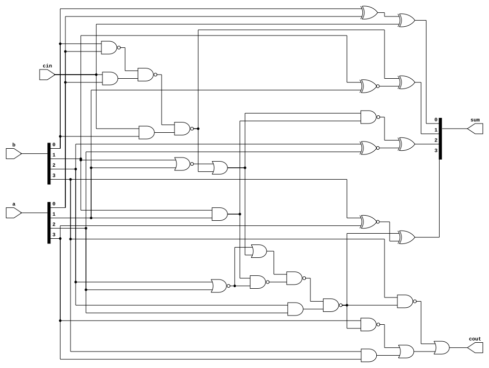
However there’s a massive problem. In hardware we don’t have polynomial fan in: we have a fan-in of 2 so we can’t compute the chain of ANDs and ORs in one step which means this circuit doesn’t have constant depth. In fact this circuit has a pretty bad \(O(n)\) depth and \(O(n^2)\) gates.
It’s not that awful though, we can speed up my circuit by computing the AND and OR chain in parallel in a similar way to how you would do a parallel tree reduction in MPI. There’s pseudocode for this on the wikipedia page for the Brent-Kung adder.
module top_module #(
parameter BITS = 4
)(
input logic [BITS - 1 : 0] a,
input logic [BITS - 1 : 0] b,
input logic cin,
output logic [BITS - 1 : 0] sum,
output logic cout
);
logic [BITS - 1 : 0] g, p;
assign g = a & b;
assign p = a | b;
logic [BITS - 1 : 0] G [$clog2(BITS) : 0];
logic [BITS - 1 : 0] P [$clog2(BITS) : 0];
assign G[0] = g;
assign P[0] = p;
logic [BITS : 0] carry;
assign carry[0] = cin;
genvar step, i, j;
generate
for (step = 1; step <= $clog2(BITS); step++) begin : loop
for (i = 0; i < BITS; i++) begin : loop2
if (i < (1 << (step - 1))) begin
assign G[step][i] = G[step - 1][i];
assign P[step][i] = P[step - 1][i];
end else begin
assign G[step][i] = G[step - 1][i] | (P[step - 1][i] & G[step -1][i - (1 << (step - 1))]);
assign P[step][i] = P[step - 1][i] & P[step - 1][i - (1 << (step - 1))];
end
end
end
for (i = 1; i < BITS + 1; i++) begin : loop3
assign carry[i] = G[$clog2(BITS)][i - 1] | (P[$clog2(BITS)][i - 1] & cin);
end
endgenerate
assign sum = a ^ b ^ carry[BITS - 1 : 0];
assign cout = carry[BITS];
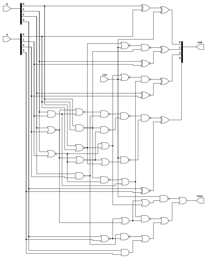
endmoduleThis looks like this as a circuit
I wrote a small cocotb test bench for this
import cocotb
from cocotb.triggers import Timer
import random

@cocotb.test()
async def test(dut):
  BITS = len(dut.a)
  for a in range(2**(BITS - 1)):
    for b in range(2 ** (BITS - 1)):
      for cin in [0, 1]:
        dut.a.value = a
        dut.b.value = b
        dut.cin.value = cin
        await Timer(1, units="ns")

        actual_sum  = int(dut.sum.value)
        actual_cout = int(dut.cout.value)
        real_sum = a + b + cin
        expected_sum  = real_sum & (2 ** BITS - 1)
        expected_cout = (real_sum >> BITS) & 1

        assert actual_sum == expected_sum, f"{a} + {b} + {cin}: expected {expected_sum=} but got {sum=}"
        assert actual_cout == expected_cout, f"{a} + {b} + {cin}: expected {expected_cout=} but got {cout=}"
It needs a Makefile and there’s a guide in the cocotb documentation
SIM = verilator
TOPLEVEL_LANG = verilog
VERILOG_SOURCES = ../parallel-adder.sv
COCOTB_TEST_MODULES = test
TOPLEVEL = top_module

include $(shell cocotb-config --makefiles)/Makefile.sim
By default cocotb uses iverilog but I changed it to verilator since that’s what I have installed on my laptop.
I had to use /* verilator lint_off UNOPTFLAT */ pragmas
to get it to work, I don’t understand why though.
After doing this I ran make and my tests all passed.
However, I’ve overcomplicated this and the site accepts the following solution
module top_module(
    input [99:0] a, b,
    input cin,
    output cout,
    output [99:0] sum
);
    assign {cout, sum} = a + b + cin;
endmodule
Even still, this was a fun exploration!